Components for ASIsafe
The concept ASIsafe (AS-Interface Safety at Work) enables the integration of fail-safe components to an AS-Interface network, such as:
Emergency stop push buttons
Safety door switches or
Safety light arrays
These are fully compatible with the renowned AS-Interface components (masters, slaves, power supply units, etc.) in accordance with EN 50 295 and can be operated together on the yellow AS-Interface wiring.
Depending on your individual requirements, you can choose between the "small" local ASIsafe Solution (standard PLC, standard AS-i Master and ASIsafe safety monitor) and cross-cell, plant-wide ASIsafe integration using the DP/AS-i F-Link, as transition from ASIsafe to PROFIsafe under a fail-safe controller (ASIsafe Solution PROFIsafe).
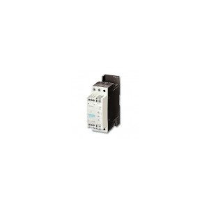
Siemens offers you the full range of components required to set up a safe AS-Interface network.
Advantages at a glance
Safe and standard data on a single bus
ASIsafe Solution local: stand-alone solution using the ASIsafe safety monitor
ASIsafe Solution PROFIsafe: linking of ASIsafe to PROFIsafe using the DP/AS-i F-Link
Allows the grouping of safer signals
Simple system configuration through standardized AS-Interface technology
Quick and easy expansion of existing systems
Overview
Transmission method
A key feature of AS-Interface technology is the use of a shared two-conductor cable for data transmission and the distribution of auxiliary power to the sensors/actuators. An AS-Interface power supply unit that meets the requirements of the AS-Interface transmission method is used for this purpose. The AS-Interface cable provided for the wiring is mechanically coded and hence
protected against polarity reversal and can be easily contacted with piercing terminals.
Function
Operating modes
Generally, master interfaces have the following operating modes:
I/O data exchange
In this operating mode the inputs and outputs of the binary AS-Interface slaves are read and written.
Analog value transfer
AS-Interface masters according to the Complete AS-Interface Specification 2.1 support integrated analog value processing.
This means that data exchange with analog AS-Interface slaves is just as easy as with digital slaves.
Command interface
In addition to I/O data exchange with binary and analog AS-Interface slaves the AS-Interface masters provide a number of other functions through the command interface. Hence it is possible, for example, for slave addresses to be issued,
parameter values transferred or diagnostics information read out from user programs.
■Technical specifications
| Standard |
EN 50295 / IEC 61158 |
| Topology |
Line, star or tree structure (same as electrical wiring) |
| Transmission medium |
Unshielded two-conductor cable (2 x 1.5 mm2) for data and auxiliary power |
| Connection technique |
Contacting of the AS-Interface cable by insulation displacement method |
| Maximum cable length |
100 m without repeater/extender;
200 m with extension plug;
300 m with repeater or extender
600 m with repeater/extender and
extension plug (parallel connection of
repeaters) |
| Maximum cycle time |
5 ms with full expansion,
10 ms when using A/B technology |
| Maximum number of stations |
31 slaves according to Complete
AS-Interface Spec. V2.0;
62 slaves according to Complete
AS-Interface Spec. V2.1 (A/B technology),
integrated analog value transmission |
| Number of binary sensors and actuators |
Max. 124 I/124 O according to Spec. V2.0;
max. 248 I/186 O according to Spec. V2.1 |
| Access control |
Cyclic polling master slave method,
cyclic data transfer by host (PLC, PC) |
| Error safeguard |
Identification and repetition of faulty
message frames |